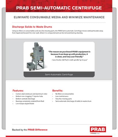
Eliminate Consumable Media and Minimize Maintenance. Discharge Solids to Waste Drum
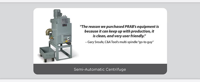
Using no filters or consumables and very few moving parts, the PRAB Semi-Automatic Centrifuge moves solid particulate away from liquid and toward the rotor wall, where it is compacted and can be removed during cleaning.
Features:
Benefits:
Backed by the PRAB Difference
High Performance Liquid/Solid Separation
Centrifuge Operation
Feed enters at the dirty liquid inlet and progresses upward through the rotor body. Centrifugal force is applied to the liquid stream in the main body of the rotor, causing solid particulate to move toward the rotor wall. Solids are deposited at the rotor perimeter while clean liquid overflows through the top of the rotor. The clean overflow discharges at atmospheric pressure via gravity through the clean liquid outlet. Solids deposited on the rotor are compacted by centrifugal force and allowed to accumulate until they are removed during the cleaning cycle. The clean cycle is manually initiated by the operator.
During the feed cycle, the lower cabinet is flushed continuously with clean liquid to minimize the accumulation of solids in that area. When the operator determines a clean cycle based on run time, the feed pump is turned off, stopping flow to the centrifuge. The drive motor is then turned off, and the rotor coasts to a full stop. Any residual liquid remaining in the rotor drops to the lower cabinet and then drains back to the process tank.
The accumulated solids are removed from the rotor as follows: First, the drain plate is slid to the open position. This movement opens the bottom of the rotor to the sludge bin below, allowing the solids to drop into it. Then the stopper pin is inserted into the block, locking the rotor in place. The t-wrench is then inserted onto the scraper shaft and rotated clockwise and counterclockwise, so the scraper cleans the solid particulate from the rotor walls, causing the solids to drop into the sludge drum below. After the sludge has been removed from the rotor, all of the above operations are reversed. The drive motor is then turned on, and the centrifuge returns to full speed. Once it reaches full speed, the feed pump is turned on, and the system operates normally. Normal operation will continue until the system is shut down or requires cleaning again.
| Model | Flow Rate | A | L | W | H | Outlet | Drain | Bowl Volume | Drive Motor |
|---|---|---|---|---|---|---|---|---|---|
| CL-50 | 15 gpm | 13-1/2″ | 26″ | 15″ Sq | 20″ | 2-1/2″ | 1″ | 1.3 gal | 2 HP |
| CL-80 | 20 gpm | 13-1/2″ | 32″ | 20″ Sq | 23″ | 3″ | 1″ | 2.6 gal | 3 HP |
Contact us to request a quote today


 (800) 968-7722
 (800) 493-3462